
[From the last episode: We can measure inertiaThe tendency for an object to keep moving (or not moving) at a constant speed if you don’t accelerate or decelerate it. There’s inertia in a straight line and there’s also inertia of rotation – spinning things want to keep rotating in a specific direction unless you force them to change. in six independent ways (degrees of freedomA setting or property that can be adjusted independently without affecting any other setting. With movement, there are three straight-line degrees of freedom: forward/backward, up/down, and left/right.): 3 in a straight line and 3 with rotation.]
We saw a couple posts ago that we can build an accelerometerA sensor that measures acceleration and deceleration. that senses when we move up or down. But last time we saw that we can measure three different directions of movement independently, not just up/down. So how do we measure the other two directions?
The answer might seem simple: just use three of these sensorsA device that can measure something about its environment. Examples are movement, light, color, moisture, pressure, and many more., laid down in different directions. And that can, indeed, kind of work – with some additional effort.
Making a Connection
First, we need to consider how we’re going to use the accelerometer: we’re not going to buy just the thing we showed in the drawing; we’re going to buy a chipAn electronic device made on a piece of silicon. These days, it could also involve a mechanical chip, but, to the outside world, everything looks electronic. The chip is usually in some kind of package; that package might contain multiple chips. "Integrated circuit," and "IC" mean the same thing, but refer only to electronic chips, not mechanical chips. that’s all packaged up, with so-called leads or places to make electrical connections. Yeah, we haven’t talked about the electrical part yet – we’ll get to that – but for now, just know that we have to make connectionsThis refers to some kind of electrical connection. It might be through a network cable, a cable connection, a wireless connection, or a phone - just to name some options. The connection might be to the internet or to some other local device..
What will we make connections to? Probably some kind of printed circuit boardSome kind of board (usually rigid) that gets metal connections “printed” onto it. Electronic components can then be soldered on. (or PCB). You’ve probably seen those before – they’re not micro-scale; they’re macro-scale.

In the picture above, you can see the different components. Some have leads that go into holes; some have leads that look more like bumps that get soldered to some of the metal. All those metal traces you see connect the different components together.
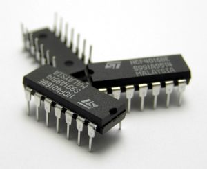
Our accelerometer could be one of those components. There are many different kinds of package and lead, but we’ll look at a particularly old-school package just because it’s easy to visualize. This package is called a dual in-line package, or DIP, because it has two rows of leads in a line. Those leads go into holes in the PCB.
Unpacking the Package
So let’s imagine our accelerometer inside one of these. We’ll first show it from the side.
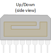
Here’s the thing: those leads are pointing down. We want to turn the inside sensor part so that it goes in one of the other directions, not up/down. But we can’t turn just the inside portion – we have to turn the entire package – and then the leads will no longer be facing down.
So we’d need to look for another version of this that was packaged with the sensor chip rotated onto its side so that the leads still face down. We can’t do that, but the manufacturer could.
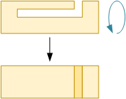
When packaged up, that gives us:
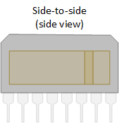
Now this one we can put down on the board in two directions, so these two packages are all we would need. To get all three directions (or three dimensions or degrees of freedom), we would place them like this (looking down from on top this time):
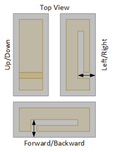
Seems easy enough, right? Well, conceptually it is, but here’s where the devil enters the details. This thing we’re doing works only if the three sensors are at exact right angles to each other. If not, then our measurements will be wrong. So that means two things:
- We must place the chip EXACTLY straight inside the package. That way we know that, if the package is straight, then the sensor inside the package is straight.
- We must place the package EXACTLY straight on the PCB. That means we have to place the holes for the pins in exactly straight lines in all directions.
Lining it Up
Believe it or not, this is actually hard to do. So if we’re going to be doing it this way, we need to calibrate the sensors because, in all likelihood, they will be just the tiniest bit off. So we need to figure out the corrections to the measurements. Which we can do, but it’s extra work.
Another option would be for the manufacturer to put three sensors in one package, something like this:
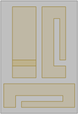
This works a bit better, since the equipment for aligning this can be more precise than what you would have when building the PCB. But still, we must place the three dice very accurately – and we still might need to calibrate.
The most precise option is to build all three out of one piece of siliconAn element (number 14 in the periodic table) that can be a semiconductor, making it the material of preference for circuits and micro-mechanical devices.. Now, instead of having to align three separate things, we’re building them so that they’re aligned. The chances for error here are very, very small. But… we can see how to build the up/down sensor with a cantilever; just building that on its side is not easy to do.
But we can do something else instead: make the proof mass as a big, thick square suspended by springs. Yes, we can make springs out of silicon (but I haven’t shown that detail; I just show springs).
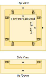
Now this one floating chunk of silicon can move up and down, left and right, and forward and backward. We didn’t have to do any aligning; we needed only to create perfect squares, and it’s pretty easy to make those (ok, they’re almost perfect…).
So here we’re measuring three degrees of freedom with a single sensor. Now all that’s left is to figure out how to turn those motions into electrical signals. That’s what we’ll talk about next.

Leave a Reply