[From the last episode: We saw that voltage has a strong impact on powerThe rate of energy consumption. For electricity, it’s measured in watts (W)..]
If voltage is a major influence on power, then, if you’re trying to reduce power, wouldn’t it make sense simply to lower the voltage as much as possible? The answer is… kinda. Maybe. It’s… complicated. But let’s go through it, since it involves an interesting new(ish) trend.
Telling the Difference Between 1 and 0
Let’s start by looking at something you’d think would be obvious: how to tell the difference between a 1 and a 0. After all, logic works by passing these 1s and 0s though a circuit, so every part of the circuit has to know whether it’s looking at a 1 or a 0 at its input(s).
First, picture a traffic light. Let’s say you are just inventing them for the first time, and you’re deciding which colors to use for “stop” and “go.” What if you picked “crimson” for “stop” and “vermillion” for “go”? Those are definitely different colors – crimson is a deeper red, while vermillion has a tinge of orange to it.
The problem is, if you’re driving up to a stoplight, can you tell, without two lights next to each other, whether it’s crimson or vermillion? Of course not; they both simply look red, and the surrounding light or your sunglasses or the windshield can even affect your perception of the color. They’re just too close together to use for contrasting values.
Of course, that’s not what we do. We have red and green – much easier to discriminate (color-blindness notwithstanding). That’s because they’re so different that a bit off here on the red or a bit off there on the green won’t matter. You still can tell “stop” from “go.”
Need a Big Gap
The same thing goes for logic. You’re going to be measuring something to decide whether a signal is a 1 or a 0. It’s typically a voltage that you’ll actually read, but that voltage is typically set up by a currentThe amount of electrical flow. Measured in amperes or amps (A). in whatever is creating that signal.
What that means is that you want a big difference between the amount of current for a 0 and the amount for a 1. Like… 1000X, 10000X, or even more. If a 1 means 10 nA (a billionth of an amp), then you’d want a 0 to be something like 10 fA (a trillionth of an amp) – maybe less?
We can see this by looking at that voltage/current curve we’ve seen a couple of times. We’ve used simplified curves before – and we’ll continue to do so – but, for this, we’re going to make a change to the chart. Some of you may be familiar with what’s coming, so thanks for your patience as we describe this for those that might not have seen it before.
A Different Kind of Graph
The graph we’ve looked at has been “linear.” That means that the distance between each mark is the same. You might start on the vertical axis with 0 on the bottom and then go up by, say, 1 mA for each tick. This works really well for a lot of things, and for the stuff we’ve been looking at, it’s been fine.
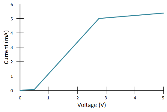
The graph below is the one we saw last time, only this time we’ve added numbers to the axes (along with the units of mA and V to the labels so that we know what we’re measuring). The numbers go up evenly by 1s. (I haven’t tried to make the actual values match a specific type of transistor; this is qualitative only).

But you see that part on the left, where it almost flattens out? What if we want to look there? We can’t really see what’s going on. We can change the way the graph works to “blow up” that area of interest. We’ll use a logarithmic scale instead of a linear one. That means that, instead of each tick going up by 1, each tick will go up by a factor of 10.
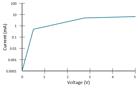
The next graph shows this. Notice that we can do this on either or both of the axes (so-called log-log if on both, log-linear if only on one). We did this only on the vertical axis for the current; the voltage is still linear.

You can see how it’s more squished at the high end, but more drawn out at the low end (and the low end never gets to zero!). We’re going to be looking at the low end, so with most of the graphs after this, we’ll be looking only at that portion.
Different Voltage “Regimes”
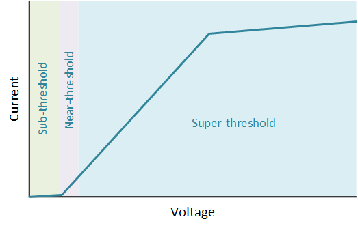
We have, so far, been using the very right part of the full curve for “on” and the left part for “off.” On the linear chart, “off” looks pretty much like no current. It’s the threshold voltageThe voltage at which a transistor starts to turn on. It’s technically "off" below that voltage, although it is still ever so slightly on. that makes the biggest difference in current, so engineers now define three areas, or regimes: the part way above threshold, called super-thresholdCircuits done where an active transistor works at voltages well above the threshold voltage; the part right down near the threshold, called near-thresholdCircuits done where an active transistor works barely above the threshold voltage, and then the part below the threshold, called sub-thresholdCircuits done where an active transistor works below the threshold voltage..

Restricting our discussion to logic (1s and 0s) for simplicity, we normally have a 1 way up in the super-threshold portion. But that’s also a higher voltage. Could we restrict operation to much lower voltagesVoltage is what gets electrons to flow. It's analogous to water pressure, which gets water to flow. Voltage is measured in units of "volts." to save energy? Yes we can, but it’s tricky. We’ll focus now on sub-threshold. That means we don’t have this convenient on/off switch anymore; we’re completely in the range of “off,” which we know in reality isn’t quite off: we’ve got leakageThe very small amount of current that can flow through a transistor when it's "off." current. And that current varies a lot if we change the voltage a little. The catch is that they’re all really small currents.
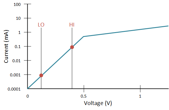
The next graph blows up that sub-threshold portion so we can see it better. Let’s say we define “hi” and “lo” as shown in red. A high voltage is about at 0.4 V; a low voltage is at about 0.12 V. Can this work?

Well, we see from the currents that a high gives us about 0.1 mA and a low gives about 0.001 mA. Those two numbers differ by a factor of a million. That’s a big enough difference that, in theory, we might be able to detect it with the right circuits.
And there are companies that know how to do this, although it’s hard. There are a couple of gotchas that you have to pay attention to; we’ll talk about one of them next week (and the other a couple weeks later).

Leave a Reply